Signal Distortion Measuring Device
Undergraduate Graduation Design
System performance requirements
- $30mV$~$600mV$
- $1kHz$~$100kHz$
- The total harmonic distortion measurement error $\Delta=|THD_x-THD_o| \leq 3\%$
- Display one cycle waveform
- Displays normalized amplitude of fundamental and harmonics to 5th harmonic
- The phone displays $THD x$, one cycle waveform, normalized amplitude of fundamental and harmonics.
Automatic Gain Control (AGC) Circuit
Automatic gain control (AGC) is a closed-loop feedback regulating circuit in an amplifier or chain of amplifiers, the purpose of which is to maintain a suitable signal amplitude at its output, despite variation of the signal amplitude at the input. The average or peak output signal level is used to dynamically adjust the gain of the amplifiers, enabling the circuit to work satisfactorily with a greater range of input signal levels. It is used in most radio receivers to equalize the average volume (loudness) of different radio stations due to differences in received signal strength, as well as variations in a single station’s radio signal due to fading. Without AGC the sound emitted from an AM radio receiver would vary to an extreme extent from a weak to a strong signal; the AGC effectively reduces the volume if the signal is strong and raises it when it is weaker. In a typical receiver the AGC feedback control signal is usually taken from the detector stage and applied to control the gain of the IF or RF amplifier stages.
— From Wikipedia
AGC Indicators
According to the requirement, the operating frequency range of AGC should include $1kHz$~$100kHz$ and the amplitude range should include $30mV$~$600mV$. Therefore, the test specifications of the design module are as follows:
- Input: Single frequency sine wave.
- Frequency: $1kHz$~$100kHz$ in $1kHz$ steps.
- Amplitude: $30mV$~$600mV$ per frequency point in $5mV$ steps.
- Output requirements: $Vpp = 3.3V$, $Vmin \gt 0V$, error $\lt 15\%$.
- Total 11500 points.
AD603
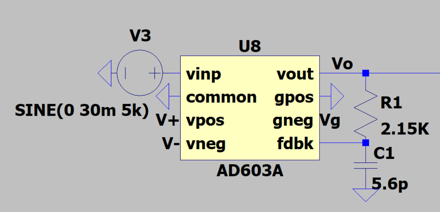
AD603 is a low-noise, voltage-controlled amplifier for radio frequency (RF) and intermediate frequency (IF) automatic gain control (AGC) systems. It offers precise pin-selectable gain ranging from $-11 dB$ to $+31 dB$ at $90 MHz$ bandwidth and $+9 dB$ to $+51 dB$ at $9 MHz$ bandwidth, and any intermediate gain range can be obtained with a single external resistor. The noise spectral density converted to input is only $1.3nV/\sqrt{Hz}$, and power consumption is $125 mW$ with the recommended $\pm 5V$ supply.
Gain is linear in $dB$, precision calibrated, and does not vary with temperature or supply voltage. Gain is controlled by a high-impedance ($50 M\Omega$), low-bias ($200 nA$) differential input; the scaling factor is $25 mV/dB$, so a gain control voltage of only $1 V$ is required to cover the middle $40 dB$ of the gain range. $1 dB$ over- and under-range is provided regardless of the range selected. The gain control response time is less than $1 \mu s$ for a $40 dB$ change.
The differential gain control interface allows the use of differential or single-ended positive or single-ended negative control voltages. Several of these amplifiers can be cascaded and the gain bias controlled by their gain to optimize the system signal-to-noise ratio (SNR).
Envelope detection
For the AGC output signal $Vo$, envelope detection is required to obtain the amplitude information.
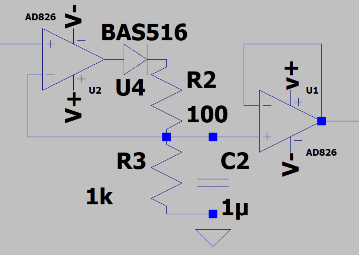
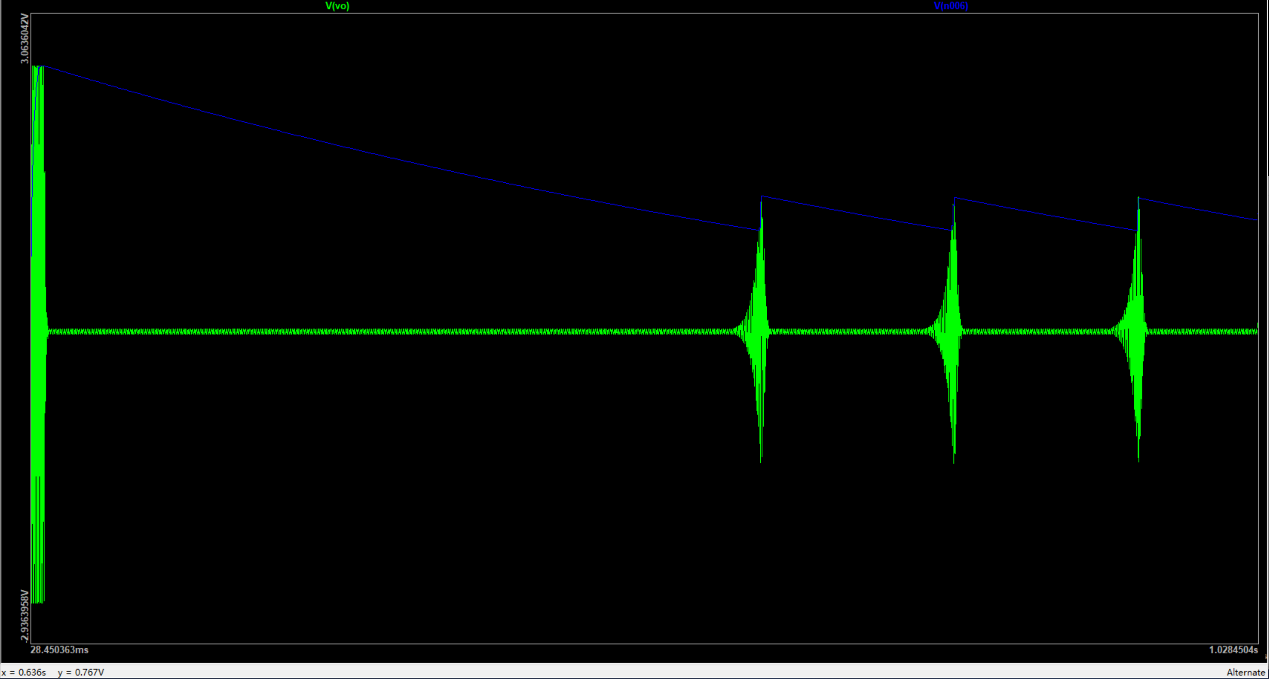
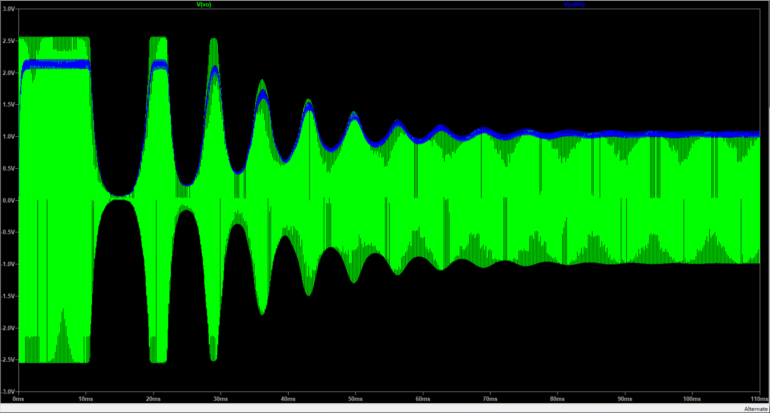
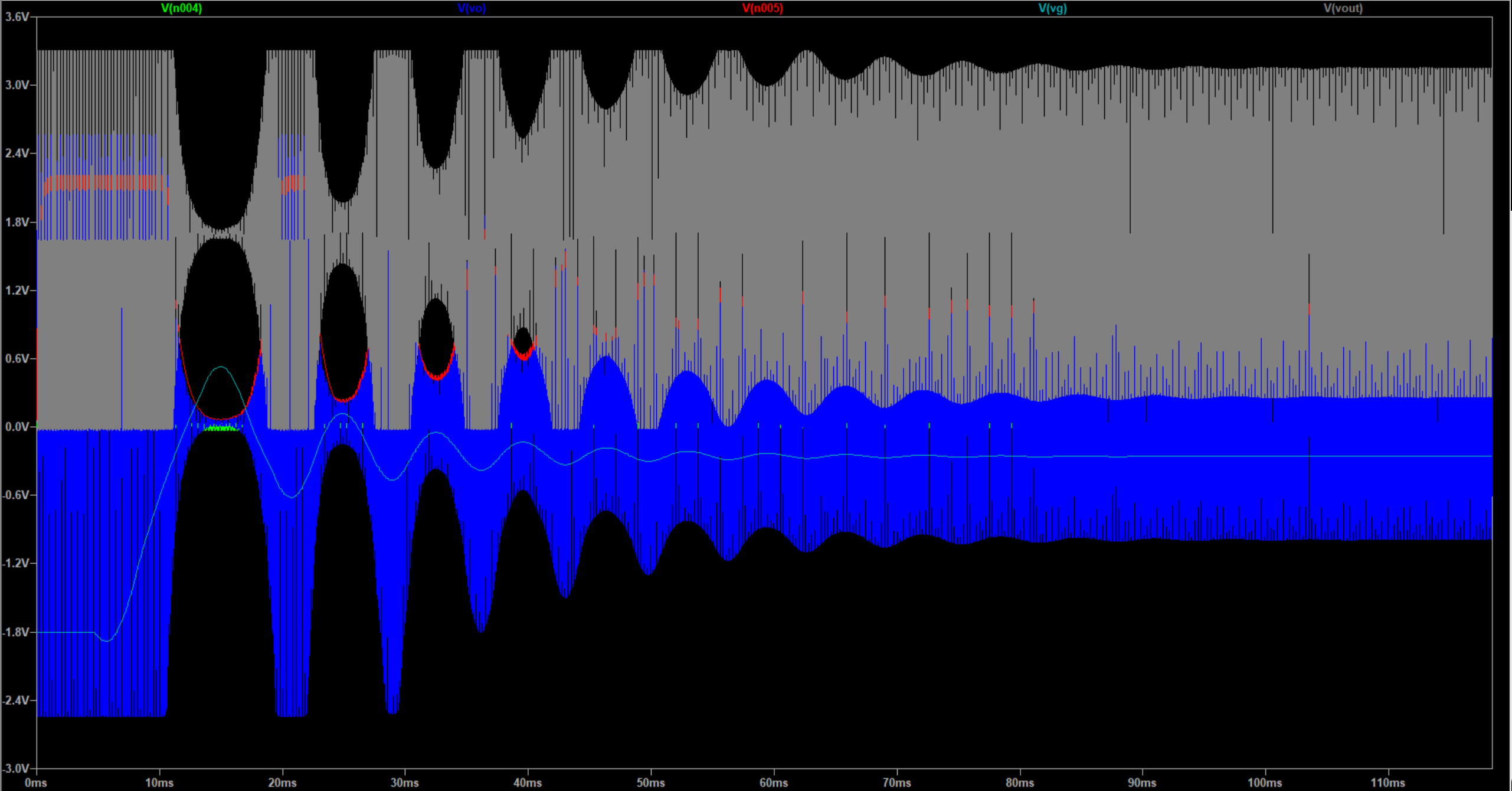
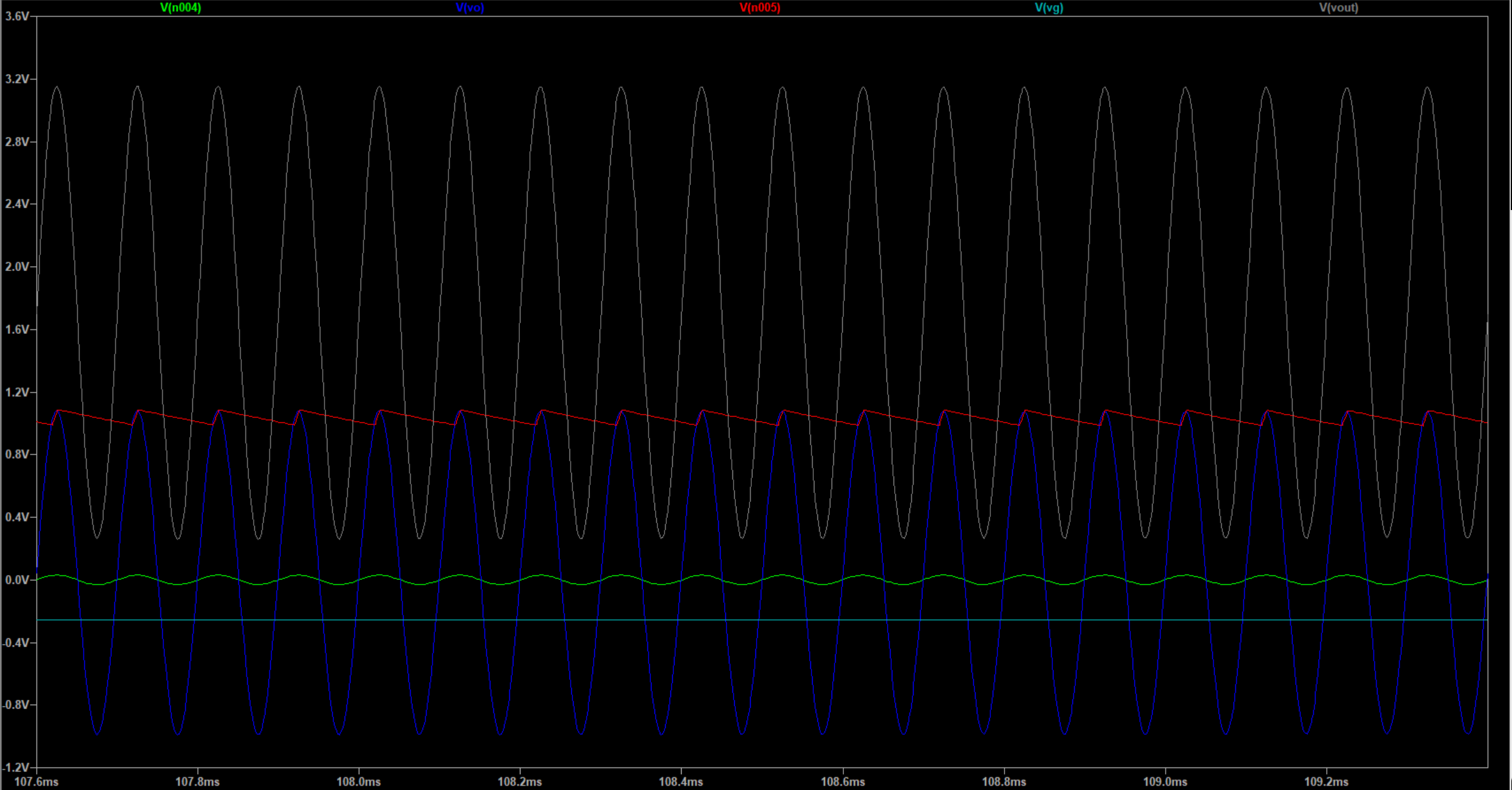
It is clear that the circuit accurately detects the envelope signal from the AGC output and, with the back stage feedback, oscillates for a period of time to control the output signal within a reasonable amplitude range.
Operate to get the feedback signal
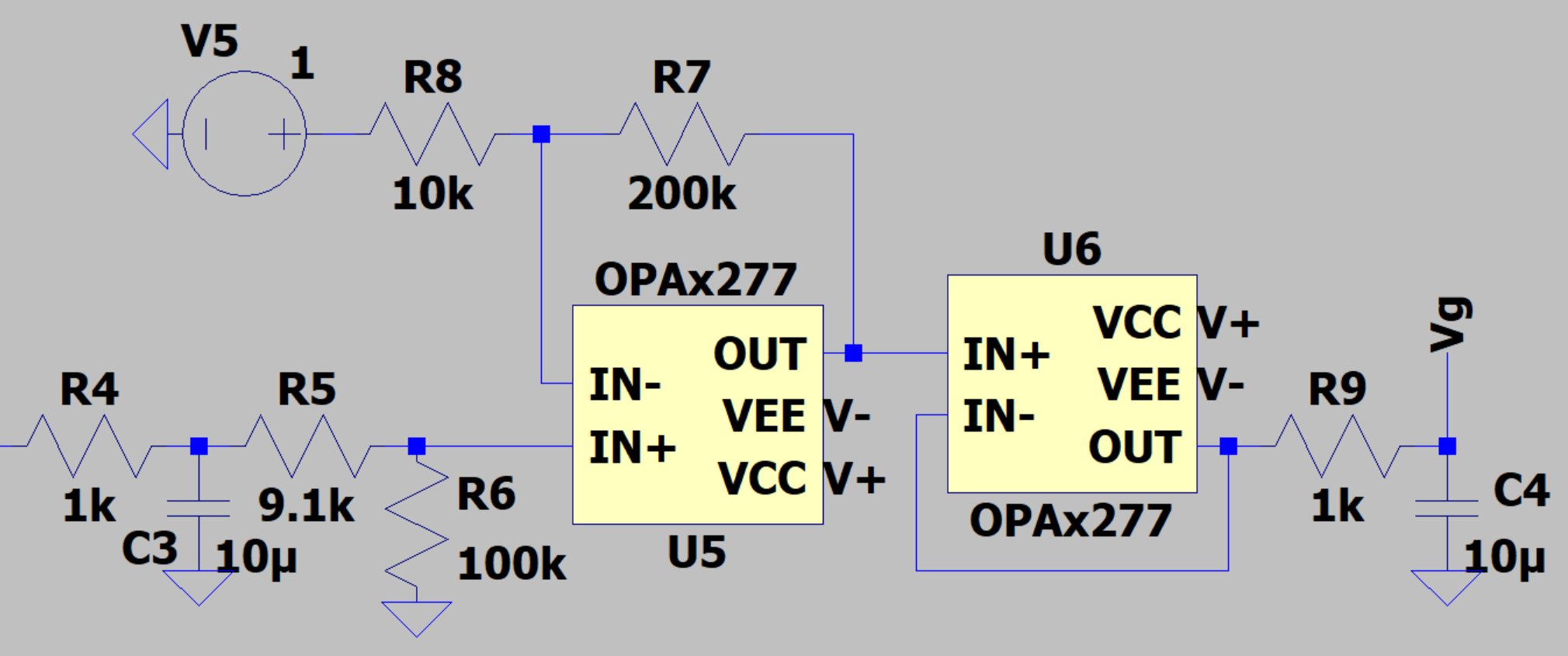
After obtaining the amplitude of the AGC output signal, we can have a reasonable AGC control terminal signal $Vg$ by linear operation of the operational amplifier.
Add DC bias
Since the analog input pins of the microcontroller have a certain input voltage range limitation, we need to add a DC bias to the AC signal output from the AGC, and a rail-to-rail op-amp OPA340 is used here.
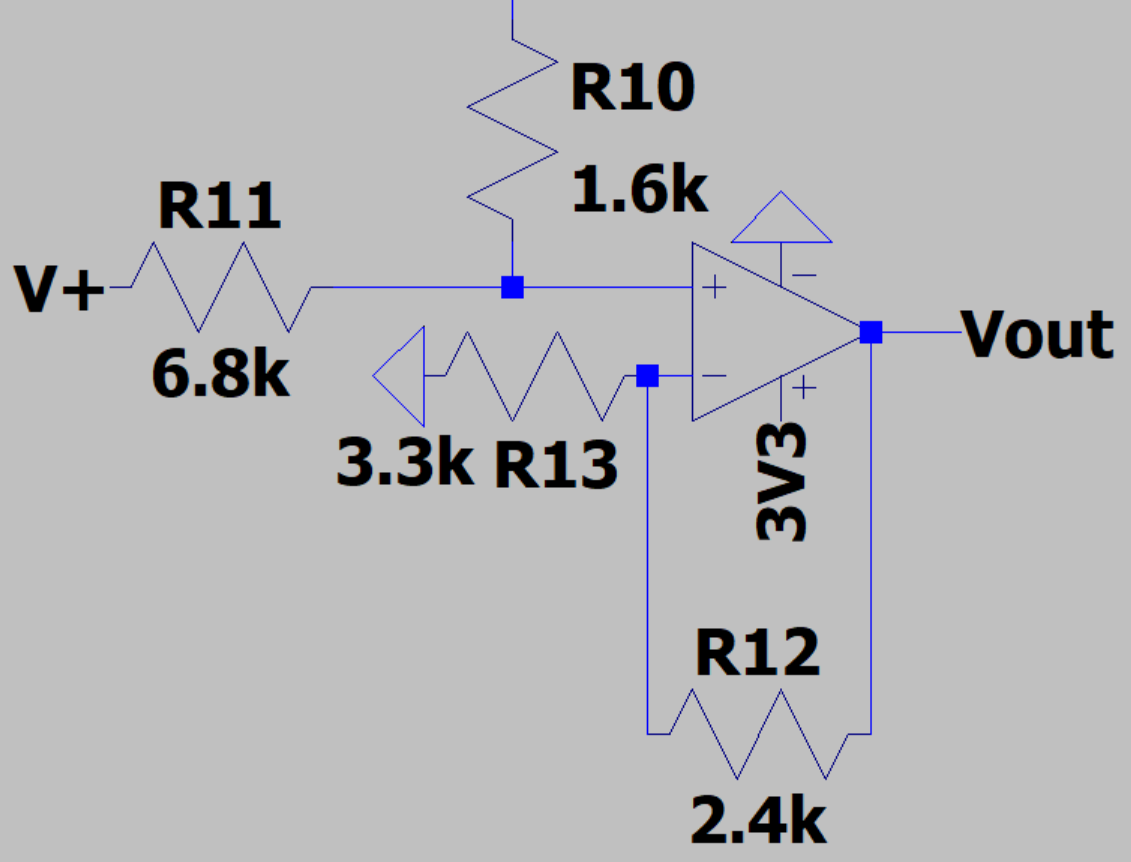
The waveforms before and after adding DC bias are shown below:
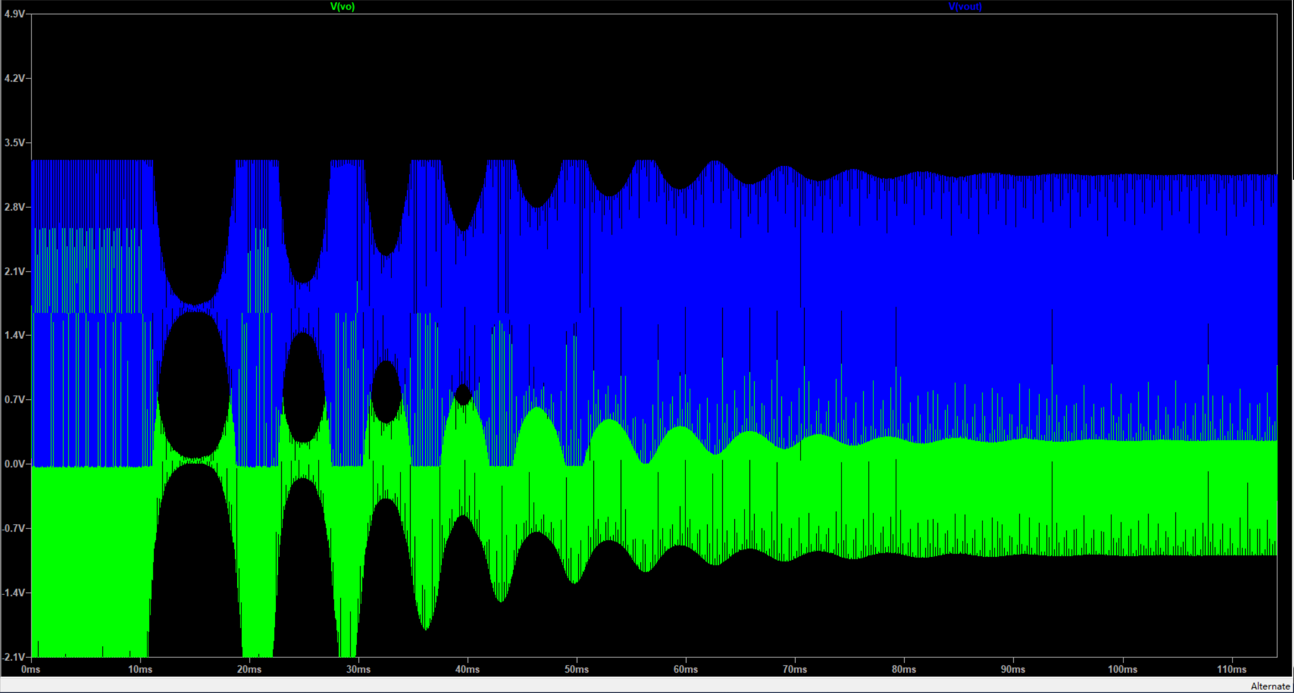
System Diagram
We used LTspice, a free simulation tool provided by ADI, to build the simulation circuit:

Set the simulation type to transient response simulation with a total duration of 150ms in 1ms steps.
